![]()
![]()
|
|
|
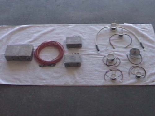
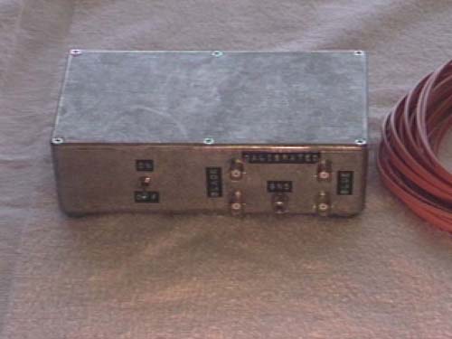
This is the complete Fiber Probe unit as designed by Terry Fritz. The unit consists of (from left to right) a receiver, dual fiber cable, two transmitters, and various current and voltage transducers.
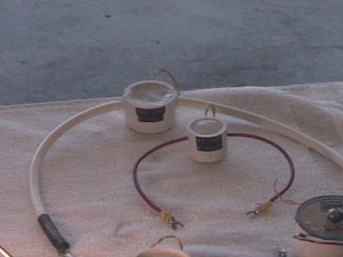
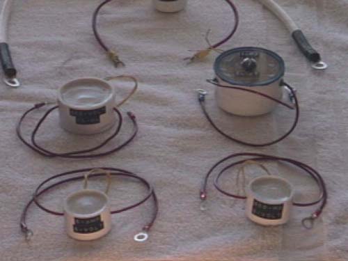
Current Transducers take up to 500a and convert it to +- 5v to send to the transmitters.
Voltage Transducers take up to +-50kv and convert it to +- 10ma to send to the transmitters.
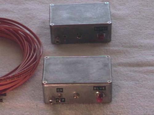
There are two transmitters which can be used concurrently. They take either a +-5v signal or a +-10ma signal and convert it to a light signal. The light signal gets sent to the receiver via a fiber optic cable. This completely isolates the test equipment from the high voltage.
Finally the dual channel receiver converts the light signal back to an electronic signal, amplifies it, and provides outputs which connect to an O-scope.
|
|
Questions and comments Copyright © 1997,2006 Brian D. Basura This site was last updated 04/02/06 |