

![]()
![]()
|
|
|
(Click on images to see a larger version)
Where to start??? The basic design criteria was for a compact controller capable of running a NST, Potential Transformer, or 10kva Pole Pig coil. It needed to include voltage and current controls, interlocks, filtering, indicators, and metering.
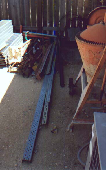
A trip to the scrap pile and a little (OK a lot) of imagination can produce all kinds of amazing ideas. Here I see a great cabinet for my new Tesla Coil Power Controller. Can you see it too???
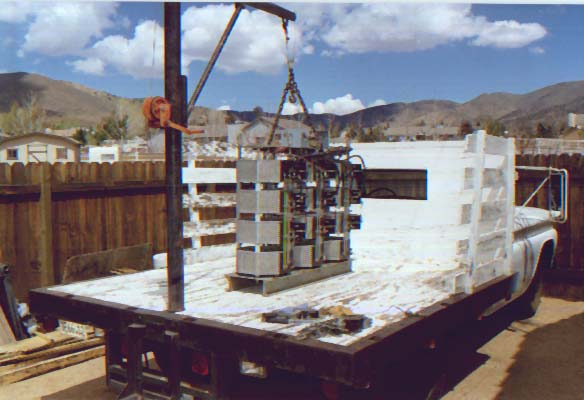
Next I need three big variable auto-transformers. Isn't this the biggest f'n Powerstat you've ever seen ? At 1100 pounds this should be big enough. Actually I used some of the individual units and sold the rest...
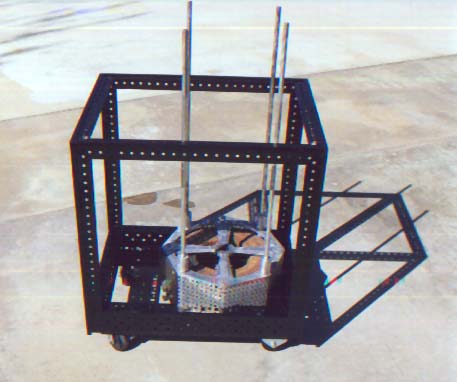
Mix in parts from the scrap pile, parts of the the big Powerstat, some visualization, a lot of sweat, and it starts to take shape. Here is the completed frame with the first Powerstat (current control/variable inductor) mounted. I'll cut and re threaded the mounting bolts after I determined their exact length...
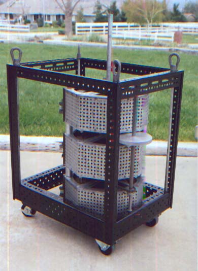
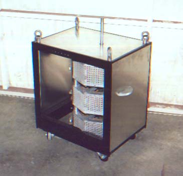
This shows all three Powerstats (1-current, 2-voltage) mounted in the frame. You can also see the current control wheel and chain drive to the lower unit. The upper two Powerstats are paralleled utilizing a paralleling inductor and share a common shaft. Also note the integral lifting hooks. These will are necessary since the completed unit will weighs close to 400 lbs...
Three skins on with two to go. This skinning process was slow going but really made the project come together. You can see the voltage control coming out the top and the current control wheel on the right...
In this phase of construction I needed to formalize the wiring. This was needed to finalize the design and figure the location of the remaining components. Click on the following to see the "As Built" schematics...
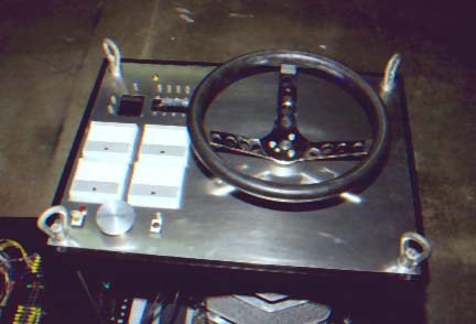
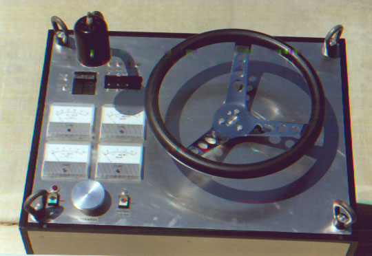
The skins are in place and I've started mounting the components. The steering wheel adjusts the voltage while the wheel on the side controls the current. You can also see the cutouts for the meters and switches. This view is from the operators side...
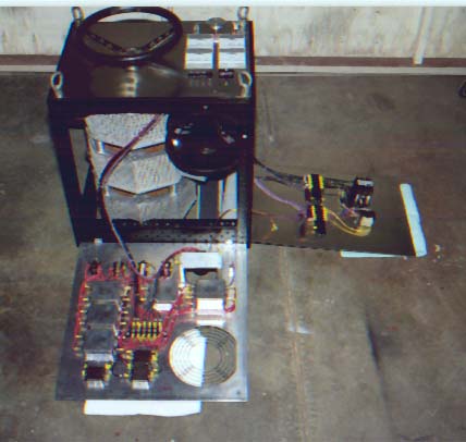
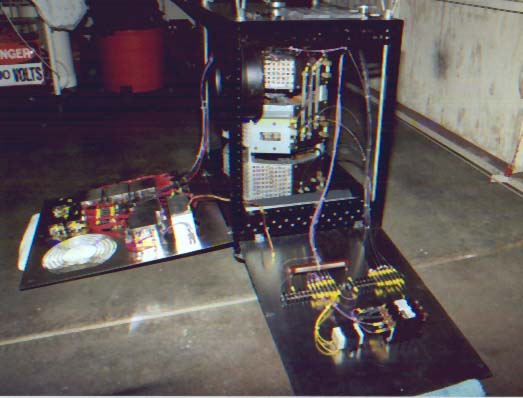
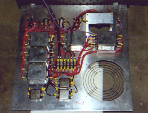
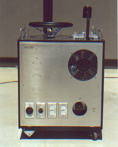
Most of the wiring is completed at this point (It was a lot more work than I anticipated!). Note the swing down panels I've incorporated to ease service. The back panel incorporates the line filtering and power connectors. The side panel incorporates the interlock circuitry. You can also see the large cooling fan which can be switched on for high KVA operation.
Almost complete... Some final testing, the resolution of a couple bugs, and labeling the indicators/switches is all that is left at this point. You can see the HV enable switch/indicator on the lower left, the local deadman switch in the center, and the interlock bypass switch on it's right.
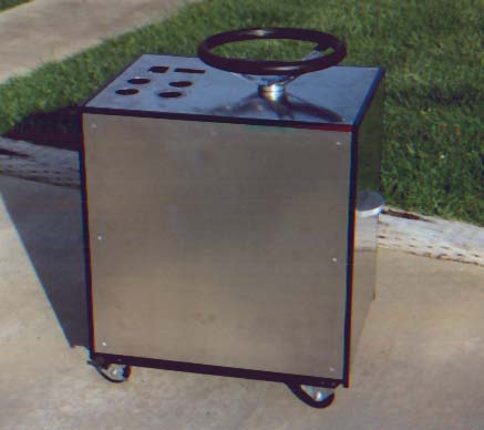
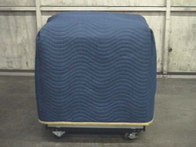
Here is a picture of the top and rear (coil side) of the unit after completion and it's blanket to keep it warm and protected.
The construction involved a tremendous amount of work but the unit should last a lifetime. :')
|
|
Questions and comments Copyright © 1997,2006 Brian D. Basura This site was last updated 04/02/06 |