![]()
![]()
|
|
|
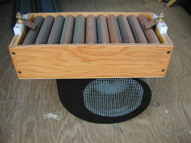
This is a simple static gap I designed. The electrodes needed to be easily cleaned and replaced. I accomplished this by grooving the PVC rods so the electrodes drop in. This unit works great up to 3kw (If one remembers to turn the blower on)...
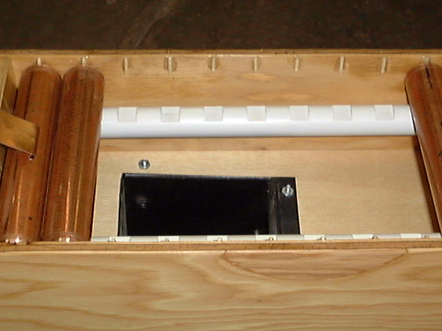
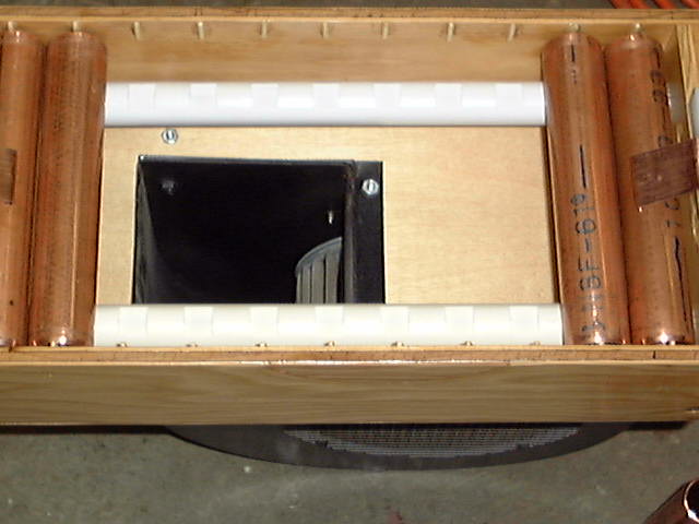
The spacers you see glued to the side of the box are toothpicks. Their purpose is increase the creepage distance between each gap. Without these spacers the ends of the pipes would touch the box and an arc would only need to creep .030" (via the side of the box). With the spacers in place the creepage distance is closer to .750" The pipe segments have a bevel on each end. This is mostly due to using a pipe cutter to cut them and emery paper used to clean up the ends afterwards. These bevels reduce voltage stresses a bit at the ends (I'm not sure it's necessary but it sure doesn't hurt). The PVC runners were cut on a small mill and it was a simple process once I figured it out. I clamped both pieces down so they were cut at the same time (this kept everything parallel). Depth of cut was deep enough so the pipe touches only on two points and not on their bottom. Spacing was determined by taking the pipe diameter and adding .030". The length of the pipes was determined by calculating the total gap area (space where air flows through) and insuring it was the optimal size for my blower. With this setup the copper pipes are almost weightless when operating. I was planning to cut a bleed hole in the side of the box if the air pressure was too much and blew the pipes off. Once finished, everything was given a number of coats of clear insulating varnish. Adjusting the total gap distance is easily accomplished by dropping in small copper tubes to short out gaps as needed.
|
|
Questions and comments Copyright © 1997,2006 Brian D. Basura This site was last updated 04/02/06 |