6.5" Tesla Coil
Design, parts and assembly of my 6.5-inch coil, from coil form to first light.
Brian's 6.5" Tesla Coil
Primary Transformer
Input Voltage
120 VAC
Input Current
18 Amps
Output Voltage
12,000 VAC
Output Current
0.180 Amps
Input frequency
60 HZ
C for Transformer Z Match
0.0398 uf
PFC Capacitance
397.9 uf
Primary Design
Inside Diameter
9.5 inches
Average Radius
8.88 inches
Wire Diameter
.025 inches
Total Diameter
26.0 inches
Wire Spacing
0.25 inches
Wire Length
79.0 feet
Total Turns
17.0
Secondary Resonant Freq.
124.2 khz
Inductance
0.1407 mh
Primary Cap needed to Resonate
0.0117 uF
Angle of Windings
0.0 degrees
Secondary Design
Diameter
6.50 inches
Radius
3.25 inches
Winding Length
27.5 inches
Circumference
20.42 inches
Wire Gauge
22 awg
Wire Length
1698 feet
Turns per Inch
37.4
H/D Aspect
4.23
Inductance
34.56 mh
Resonate Frequency
248.1 khz
Medhurst_K
0.72
Resonate Freq. w/Toroid
124.2 khz
Self_C
11.91 pf
Top Load C
35.61 pf
3.5"x23"=25.51 pf
3.5"x18"=21.97 pf
(25.51+21.97)*.75=35.61 pf
Tank Capacitors
Number of Capacitors
Capacitor Configuration
Series/Parallel
Type
Rolled LDPE
Overall C
.042 uf
Overall V
22kv rms minimum
C of each unit
.042 uf
Dielectric Constant
2.0
Plate Length
120 inches
Plate Width
14 inches
Dielectric
.036 inches (6@.006")
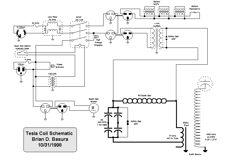
Schematic
Note: This design is now obsolete and replaced by a full power controller.
Secondary Coilform
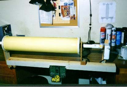
Here is my Secondary ready for winding. I've placed a 1" PVC
pipe through the center and attached it to an old rotisserie
motor with a screwdriver shank and some epoxy.
The coil form is 6" SDR35 PVC which has an OD of 6.5" and has a
27.5" winding area. The form has been sanded, dried and coated
with three coats of Spar Varnish. It's now ready for winding.
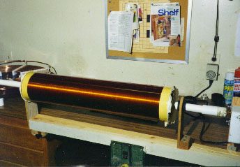
Here is my completed Secondary Coil. It's constructed of 1000 turns
of 22 gauge enameled wire with many coats of Spar Varnish.
Primary
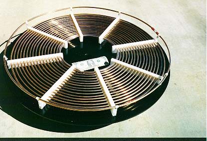
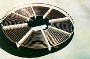
Here is my completed Primary Coil. It's constructed of 1/4" copper
tubing setting on HDPE spacers. I machined the spacers and clamps
from a HDPE breadboard. The Dollar bill is for size comparison.
Turn to turn spacing is 1/2" on center or 1/4" between windings. The
inside diameter is 9" with an outside diameter of 26".
Primary
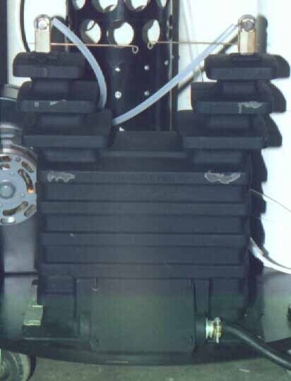
This Potential Transformer is being run backwards from it's intended purpose. I'm feeding it 120 vac (current limited) and it's outputting 12,000 vac. It was purchased from Bill Wysock at wysock@ttr.com
Primary
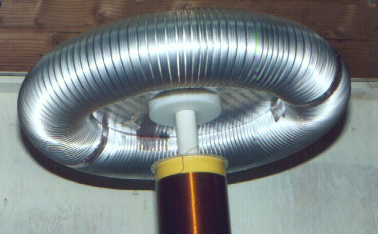
Here is the third toroid I built. It's constructed of 6" drier duct with a pressboard center covered with Al tape. It was very hard to get this toroid to break out until I started increasing the power.
Rolled Caps.
Giant Rolled Capacitors
Note: These have been rendered obsolete and I now use EMMC's exclusively.
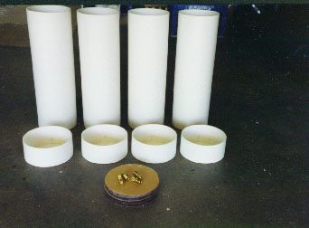
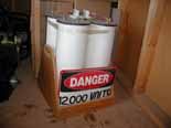
The tanks are made of 6" SDR35 PVC, 18" tall. I've glued 1"
spacers in the end caps to keep the capacitor roll off the bottom.
The top covers are 3/8" Lexan with 1/4-20 binding posts. I've
also included Schrader valves for evacuating the air and filling
the units with oil.
The configuration will be four caps in a series/parallel
arrangement to get the breakdown voltage I want. I'm planning on
a total capacitance of .042ufd.
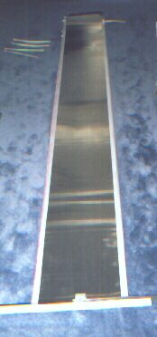
I have an aluminum plate, then six pieces of 6 mil poly, another aluminum
plate, then six more pieces of 6 mil poly. The buses are 1" aluminum strips attached to the plates with #10 screws. These screws were then smoothed and covered with a layer of silicone to help prevent punctures in the poly.
We took a piece of 1" PVC, slit it lengthwise, then used it to hold and roll the plates. You can see it at the bottom of the picture.
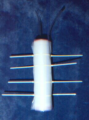
Here is how it looked after rolling and securing with large wire ties. NOTE: Rolling this beast was definitely a two or more person operation. Thanks to my wife all four capacitors rolled tightly and performed as expected.
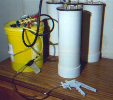
I used my "Mighty Vac" hand pump to pull a vacuum. On the first capacitor
I broke the bottom of the case when I pulled over 20" of vacuum. Next
time I'll strengthen the SDR end cap by adding a Lexan disk before gluing it onto the PVC pipe. Remember:Test your containers integrity early on!
The filling process was quite simple. First pull a vacuum then let the oil (Shell Diala-AX) drip slowly back into the tank. Make sure you allowing plenty of time for it to wick up between the poly sheets and plates.
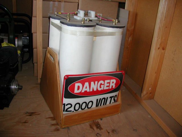
I've retired them after many hours of good service (they are looking for a good home)...
RQ Spark Gap
TCBOR/RQ Style Spark Gap
My implementation of the basic TCBOR/RQ static gap.
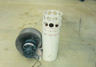
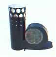
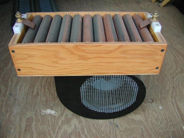
Here is the Spark Gap unit as assembled for testing. There are nine copper
pipes placed inside the 6.5" SDR35 PVC. I have also added internal baffling
to increase air flow between the gaps and a top cover.
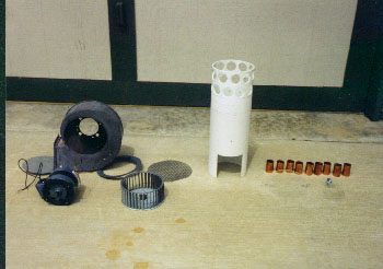
Everything has been taken apart, cleaned, and is ready for painting.
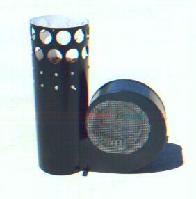
Here is the completed unit as initially completed.
As power was increased it became necessary to fabricate internal baffles forcing the airflow between the gaps. I've since retired this gap and use my new static gap when not running a RSG in synchronous mode.
First Control Box
Note: This has been scrapped and I now use my new power controller!!!
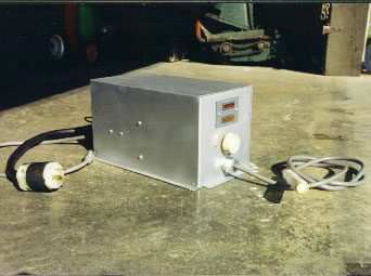
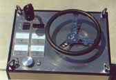
Here is the outside of my control box. It contains filters, fuses, indicators,
blower control, and a "Dead-Man" switch for the HV.
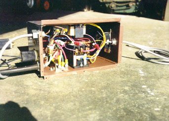
This is the inside of my control box. You can see the contactor, LV transformer,
fuses and line filters. There is also a outlet on the back for series current
limiting ballast if needed.
Coils and Parts
Tesla Coils
A "Horizontal-Bipolar-Tube-Coil" I'm building
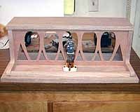
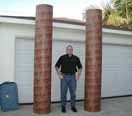
Something BIG is in the works!!!
Ross standing with the secondary forms for the new R&B Tesla Coil
My original 6.5" Tesla Coil
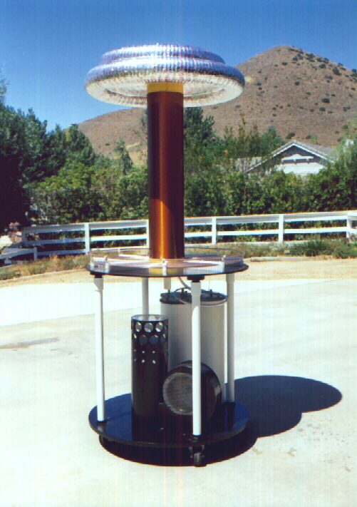
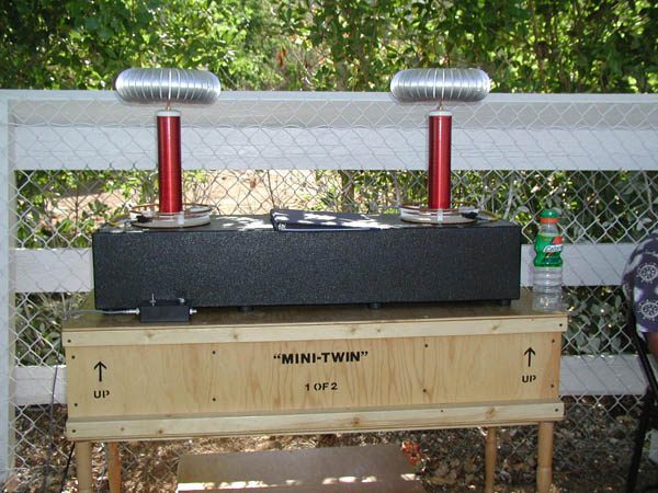
The Mini-Twin bipolar Tesla Coil
Bruce's Coil
(I built it for my brother)
Parts, Parts, and more Parts
The original Secondary coil for my 6.5" Tesla Coil
Shiny new Primary coil for my 6.5" Tesla Coil
Rolled Poly Caps
These homemade caps served me well
TCBOR/RQ
Style static spark gap
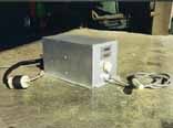
My first Control Box
It's now obsolete and has been scrapped
Power Controller
This is my 10kva power controller with internal inductive current limiting
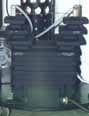
Potential Transformer
Ran backwards it gives me 12,000 volts
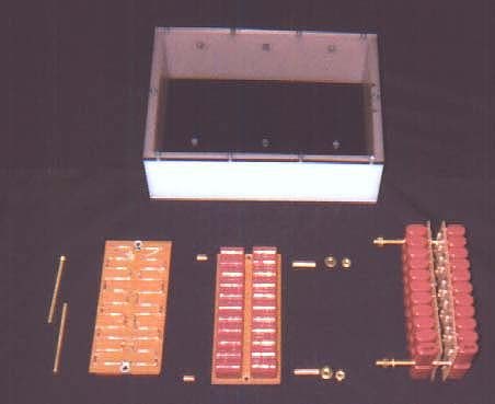
MMC Capacitors
These have replaced rolled, plate, and other types of home-built tank capacitors
Rotary Spark Gap
This was a great learning experience
High Power Static Spark Gap
This gap is capable of sustained operation at power levels over 3kva
DC Conversion
I'm working up a method of charging the tank cap from HVDC
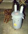
Pole-Pig Diet
I gutted this pig, chopped down the tank, and re-animated it
Spun Aluminum Torroid
New Secondary Coil
Higher inductance and a bit longer
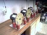
Some of the SRSG's
Assembly 1
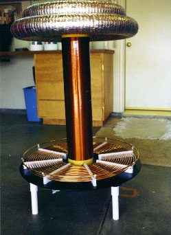
Here is the first look at the main sub assembly. The Secondary and Toroid can be
adjusted by adding or removing 1/4" spacers.
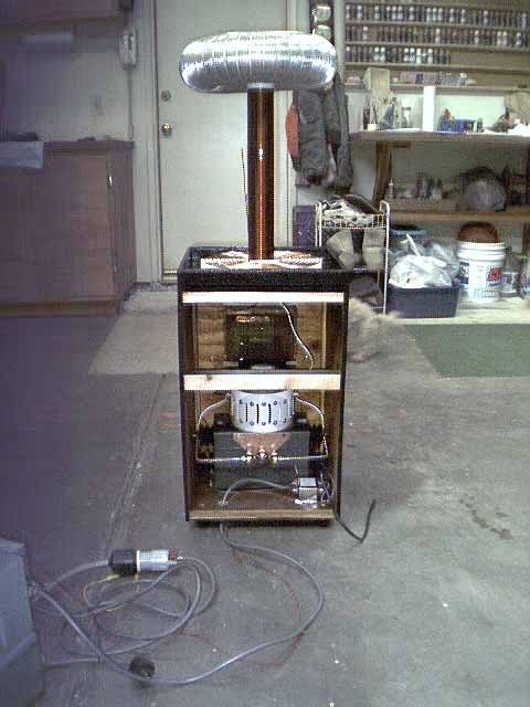
Completed
Most of my coil is completed at this point. But, I was still looking for a Potential Transformer to supply my HV.