Home / Backyard Science & Workshop
The Quarter Shrinker
A pulse-discharge machine that shrinks coins with a massive magnetic pulse.
Shrunken Quarter
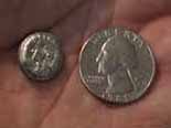
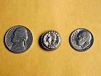

The PDM Machine
(aka "Quarter Shrinker")
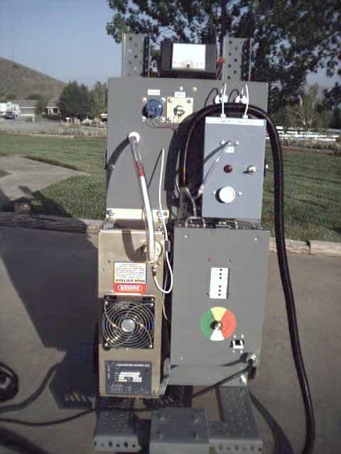
This picture shows the front of the machine. On the lower left is the HV Power Supply. On the lower right is the control box which houses the control circuitry, low voltage transformer, and air compressor.
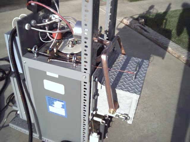
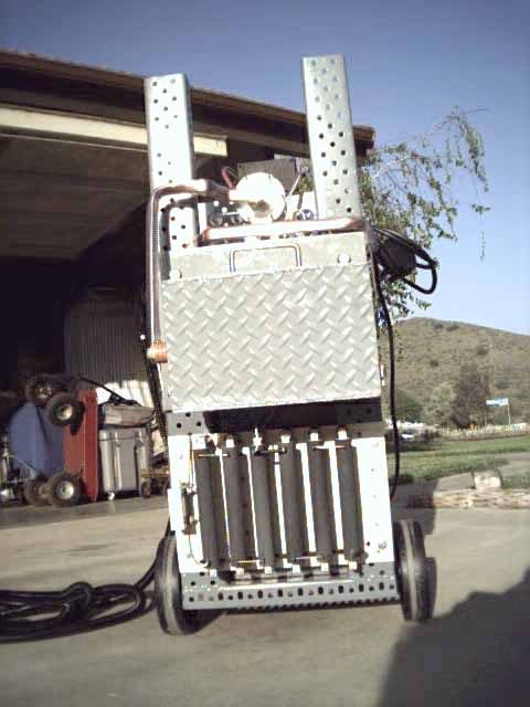
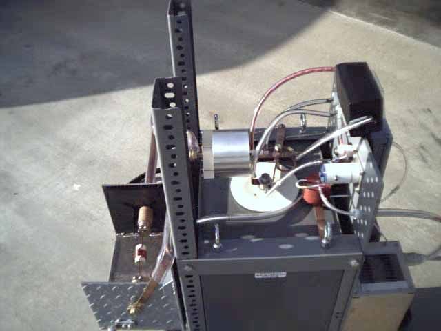
This shows the right, rear, and left views of the machine. If you look closely you can see the buss bars, safety lockout, trigatron, and discharge resistors,
Work Coil
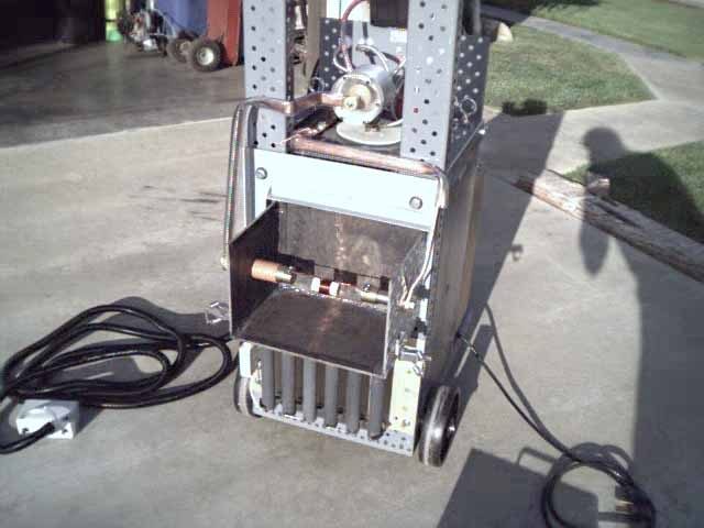
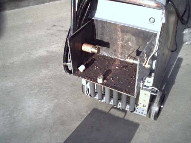
The picture on the left shows a work coil in place and ready for a shot. The second picture shows the results after the shot. If you look closely you can see the shrunken quarter just to the right of the wooden dowel. also note the wire shrapnel all over the inside of the containment.
What it does
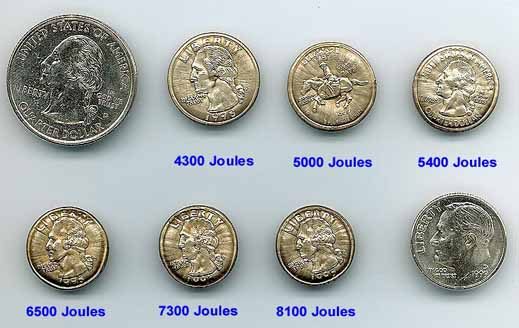
How it Works
How it works
The machine uses high-velocity electromagnetic forming, also called magneforming. A large bank of high-voltage capacitors is dumped through a small coil of heavy wire wrapped around the coin in a fraction of a millisecond.
That pulse induces an enormous current, hundreds of thousands of amperes, in the rim of the coin. The opposing magnetic fields push the coin inward, squeezing it to a smaller diameter, while the work coil itself is blown apart. That's why the coil sits inside a heavy containment box.
For a much deeper explanation of the physics, see Bert Hickman's excellent write-ups on capacitor discharge coin shrinking.
Block Diagram
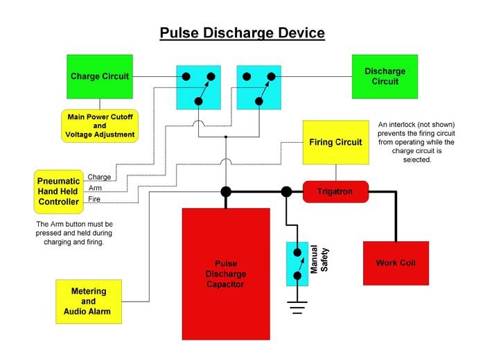
Safety and reliability were primary factors in this design.
Schematics
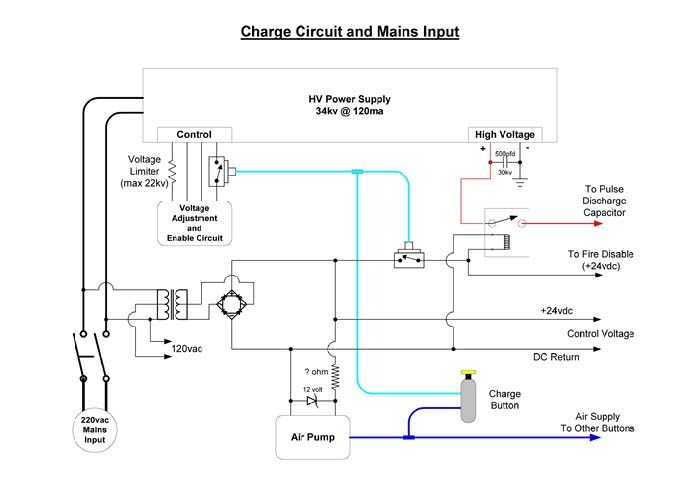
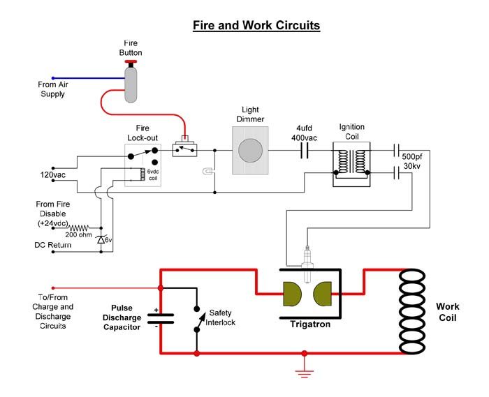
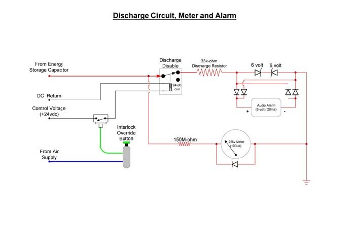
These show how things are actually hooked up.
Calculations
Pulse Discharge Workbook.xlsExcel spreadsheet · 32 KBThis workbook gives energy calculations as they relate to a particular charge voltage. It also provides peak and average power dissipation calculations for the bleeder resistor network.
Construction
High Voltage Capacitor Charging Supply
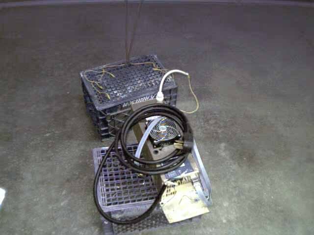
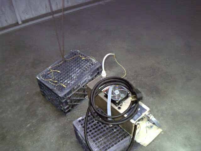
This is a 34kv power supply which is designed to charge capacitors at a rate of 1kJ per second. I've limited the controller so it's only capable of 22kv. This will help prevent over volting the capacitor.
Trigatron
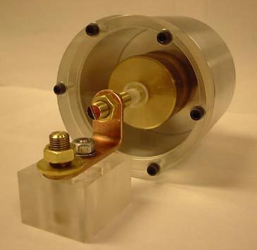
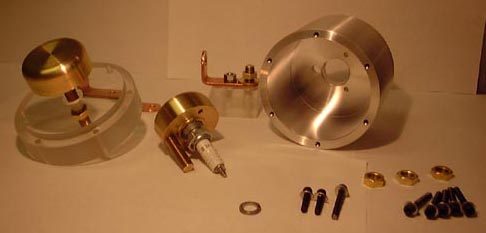
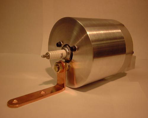
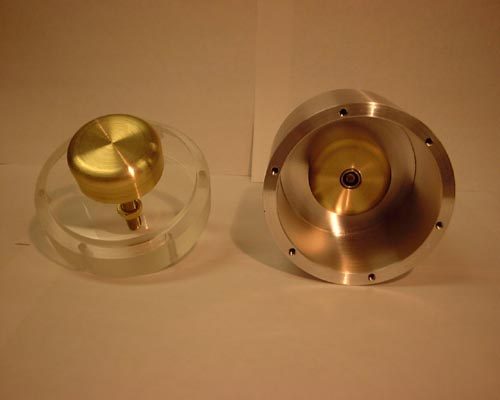
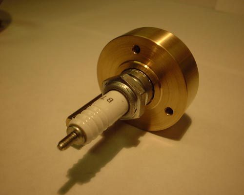
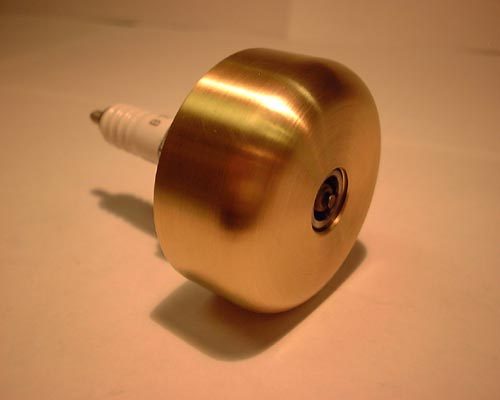
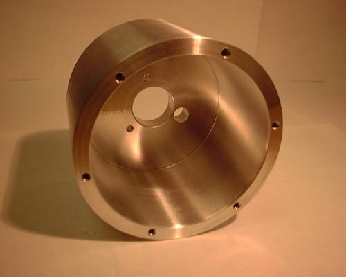
A Trigatron is a fast acting, high voltage, high current switch which is triggered by a high voltage arc inside of the main body. This design uses a modified spark plug as the trigger electrode.
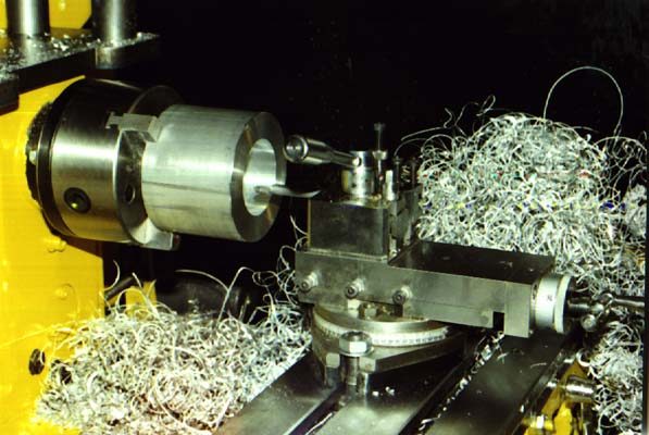
This trigatron is one of two units I hand fabricated. The other unit is installed in Ross-O's PDM machine.
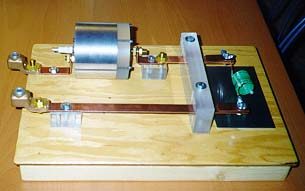
This is the prototype trigatron base and bus bar configuration. The pulse cap was hooked up via the 2ga screw down connectors on the left and the quarter went inside the coil on the right hand side of the photo. This is the 2nd of 2 units we fabricated. Turns out that the blast force was much more than we anticipated.
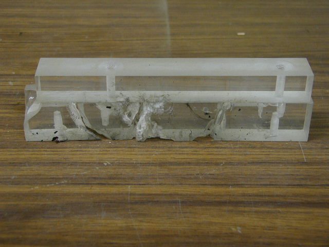
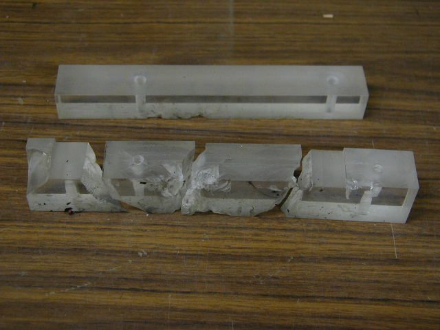
Extensive damage was done to the blast plate, wooden base, and 1.25" thick Lexan when the diamond plate containment box was fitted over the quarter shrinking coil and the fire button was pushed! Regardless, with a little last minute engineering we managed to make this unit hold up for 8 or 9 quarter shots.
Trigatron Firing Circuit
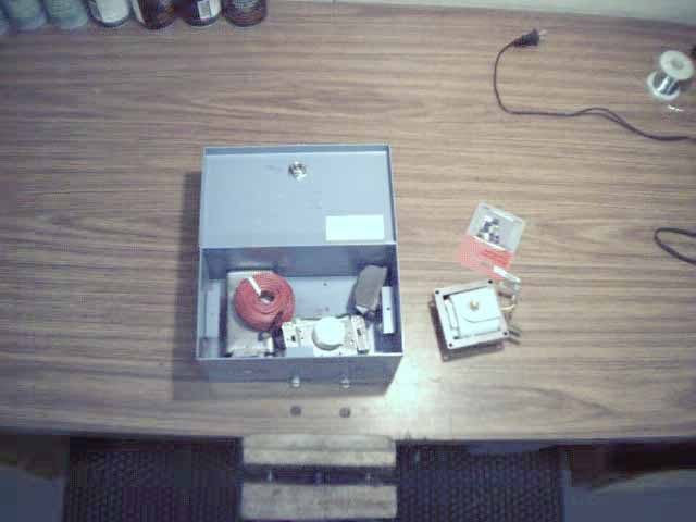
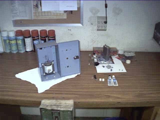
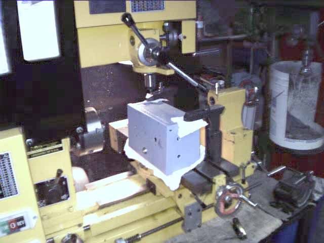
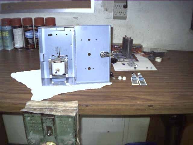
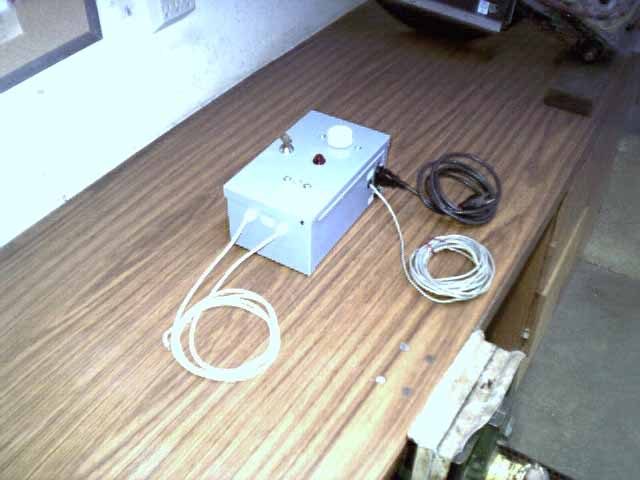
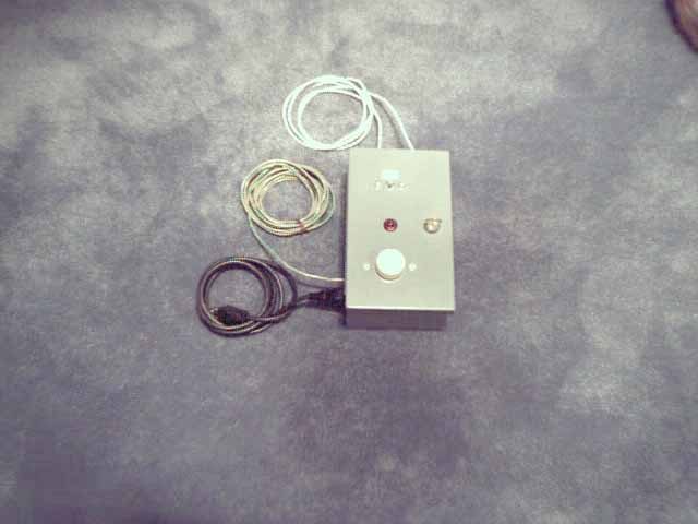
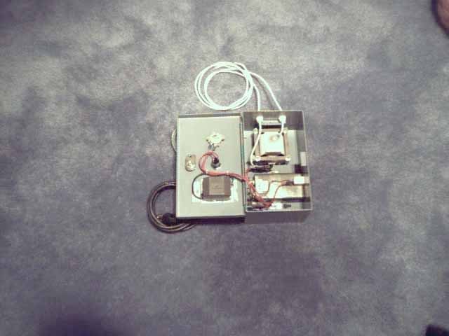
This method was recommended by Bert Hickman. It is simple, inexpensive, and will produce about 1" arcs from either a standard ignition coil or a HEI coil. The light dimmer can be found at Home Depot or similar stores.
Pulse Discharge Capacitor
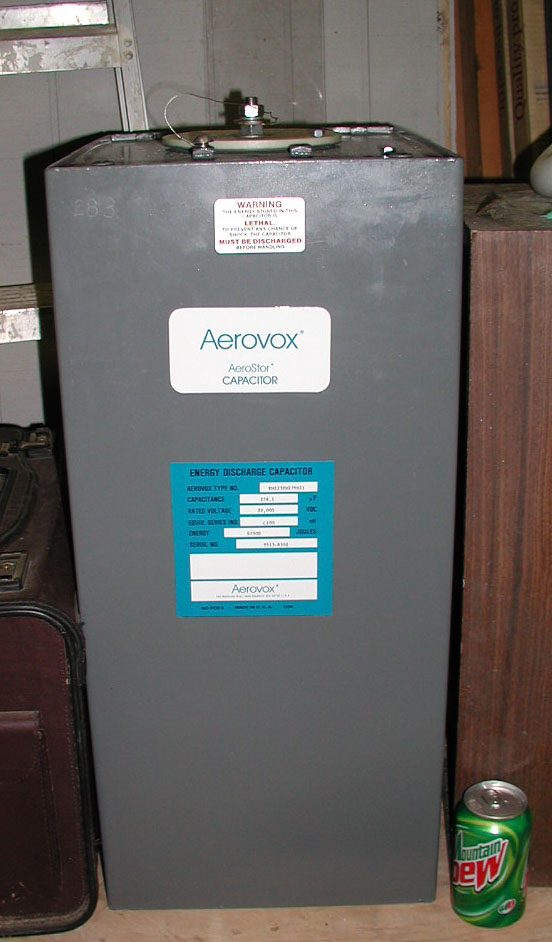
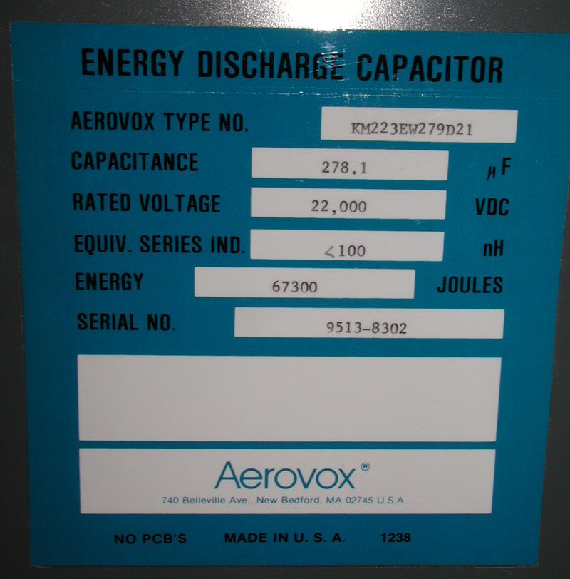
This unit is capable of storing and discharging over 67kJ of energy. Shrinking of a quarter takes only 4-9kJ. This is an extremely deadly and deceptive component. Utmost care need to be taken whenever working with or near this capacitor.
Main Control Box
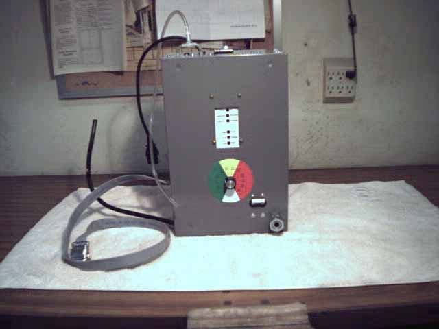
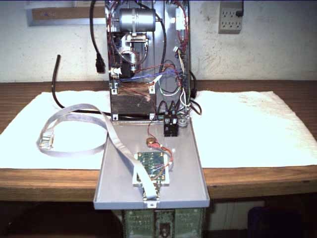
This box houses the 240v mains isolation transformer which also provides 120vac to the Trigatron firing circuit. It also contains the power supply control board, charge voltage adjustment, status indicators, air pump, air reservoir, pneumatic switches, and other control circuitry.
Pneumatic Controller
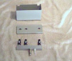
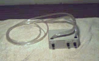
This is the hand controller which allows the operator to override the interlock, charge, and fire the PDM machine. Safety is a primary concern with this machine so I've designed it with complete isolation for the operator. To accomplish this I use air pressure to control the functions eliminating any wires between the operator and the machine.
Cart
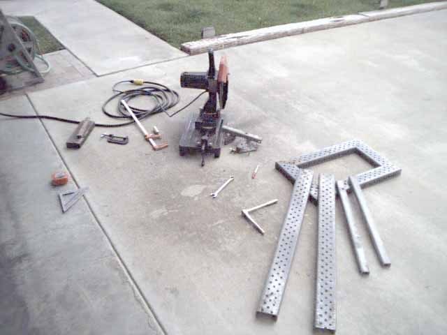
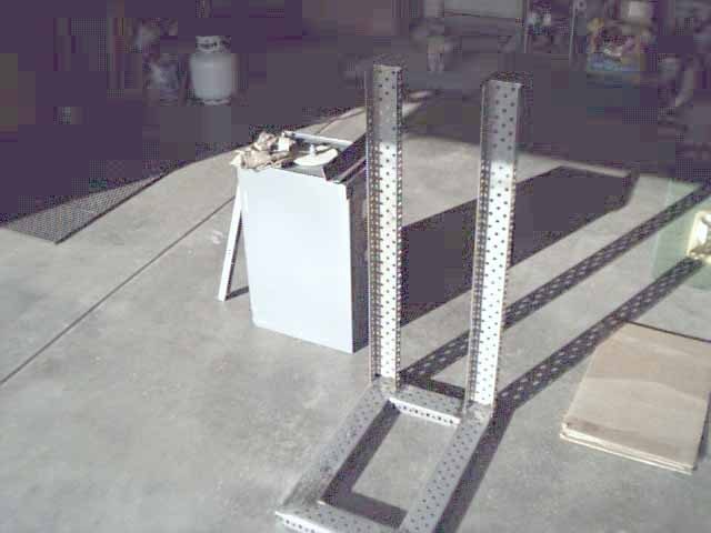
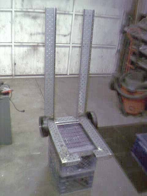
I'm attempting to build a cart that is half hand truck and half cart. If all goes well it will tip back on two wheels for moving between locations. It will also have a third front wheel to ease in positioning while in use.
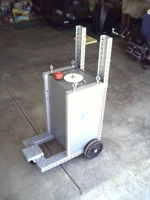
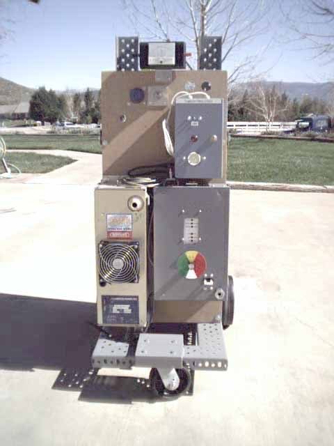
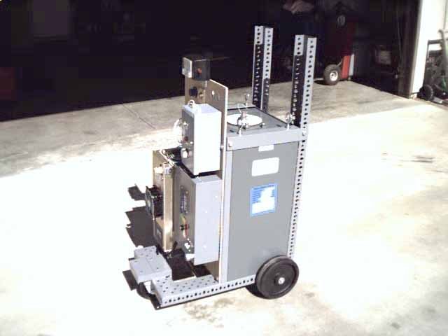
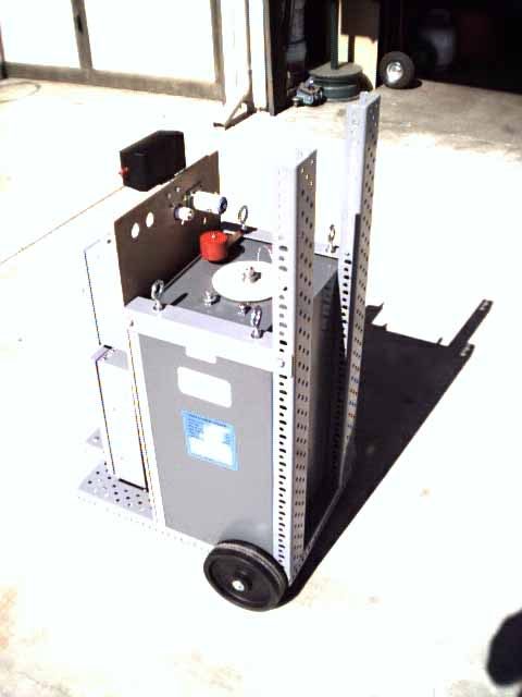
All the major components are mounted. I now need to disassemble it, paint the mounting board, then re-assemble.
Containment
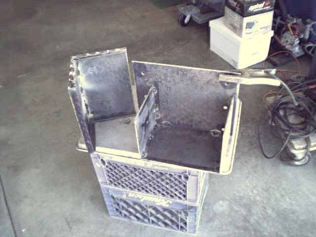
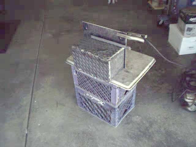
The containment box is made of 1/4" steel diamond-plate. The lid has overlapping seams to prevent fragments from slipping between the mating surfaces. The first shot shows the inside with the lid removed. The second shot shows the unit with the lid installed. I still need to add the catches, HV insulator and binding posts.
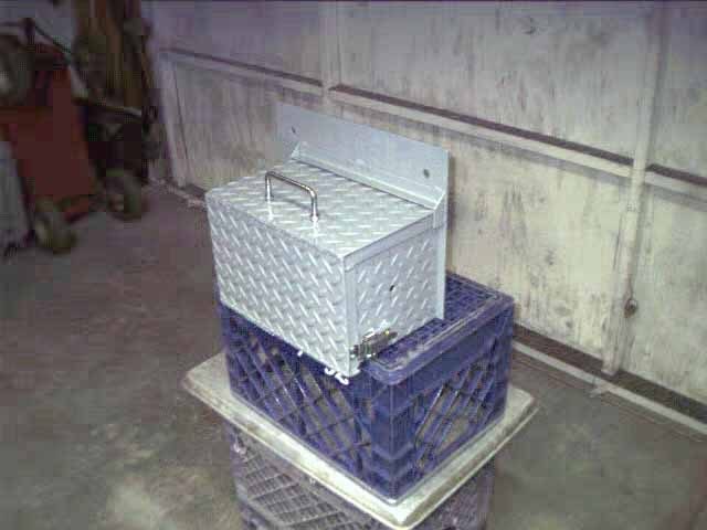
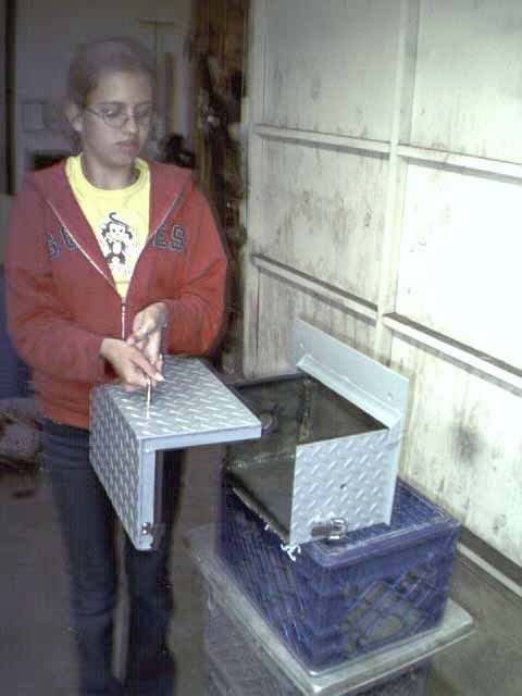
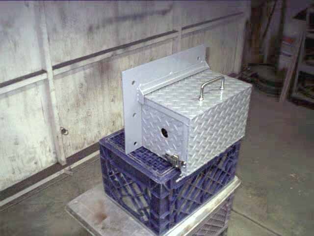
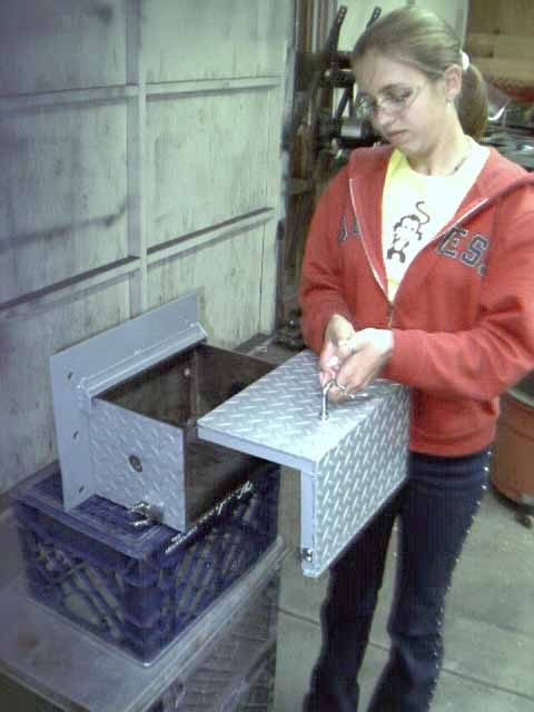
Some better pictures of the containment and how the lid operates.
Completed PDM
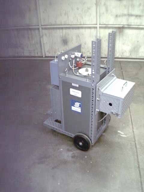
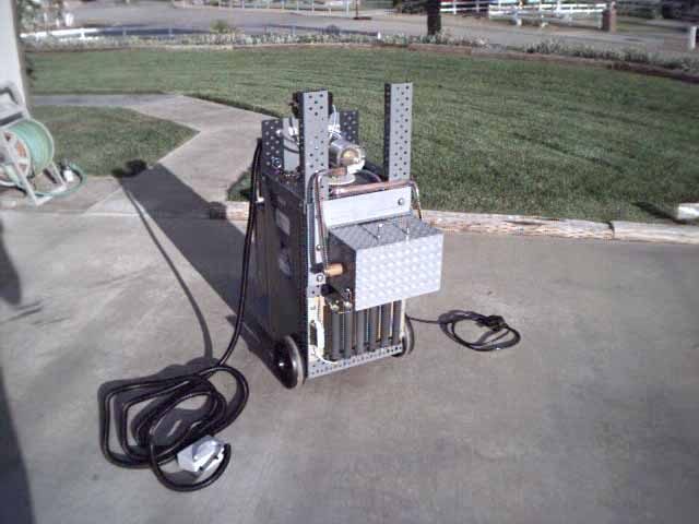
The first picture shows it nearing completion. The second and third pictures show the completed unit (minus some lexan shielding around the top HV wiring). The black cable on the left is four air hoses in a corrugated sheathing. These hoses carry supply air and control signals to/from the hand-held pneumatic controller.
The Accident
Revision 2
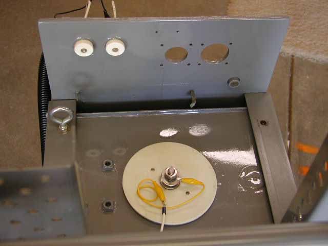
The machine has been cleaned of all the carbon from the accident and re-painted. It's now ready for re assembly.
The Trigatron had over 100 shots on it so I decided to pull it apart and see what was going on inside before I put everything back together.
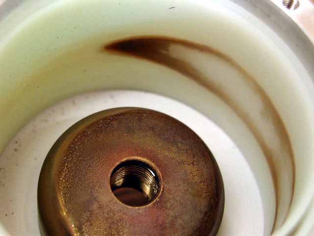
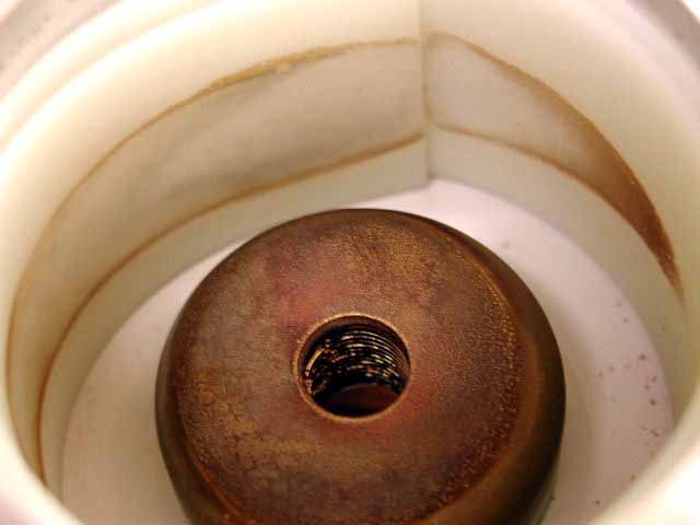
You are looking inside the Trigatron at the HDPE liner that surrounds the trigger electrode. Notice the strange pattern which has been deposited on it. Wiping the liner with a paper towel removed half of the deposits and left the towel with a green residue on it.
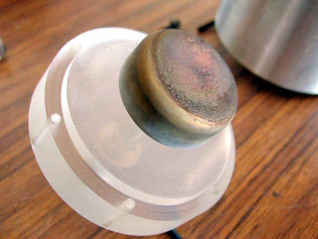
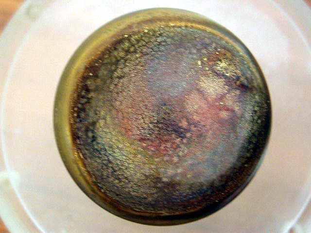
There was some wear on the solid electrode although it was mostly pitting. The abuse this electrode took left its surface marked with an interesting array of colors.
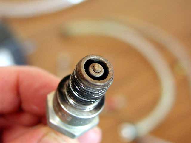
The trigger (aka - Sparkplug) shows deposits of brass on its tip. These deposits look like tiny beads of brass.
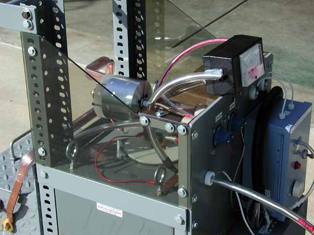
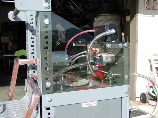
Lexan blast shields were added to the sides and over the top of the contactors. In the event of an arc-over this should help direct the blast away from the operator and contain some of the exploding wire fragments.
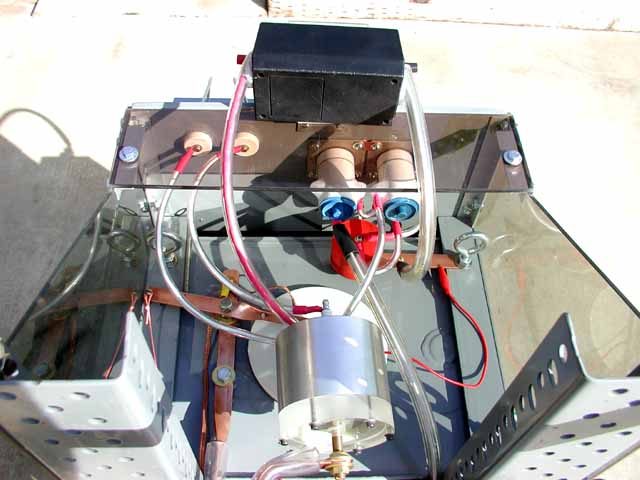
The HV wiring was cleaned up and routing carefully redesigned to prevent voltage stresses wherever possible. HV lines were all double insulated and the connections potted in silicone. Ground wires were triple insulated and routed clear of HV wires.
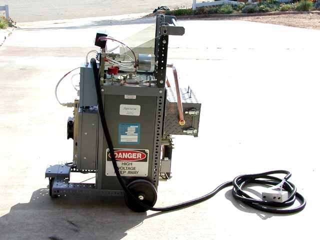
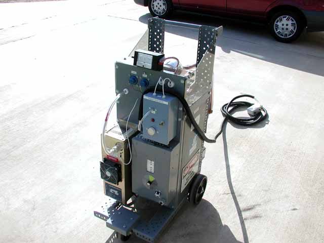
Here it is ready to be tested.
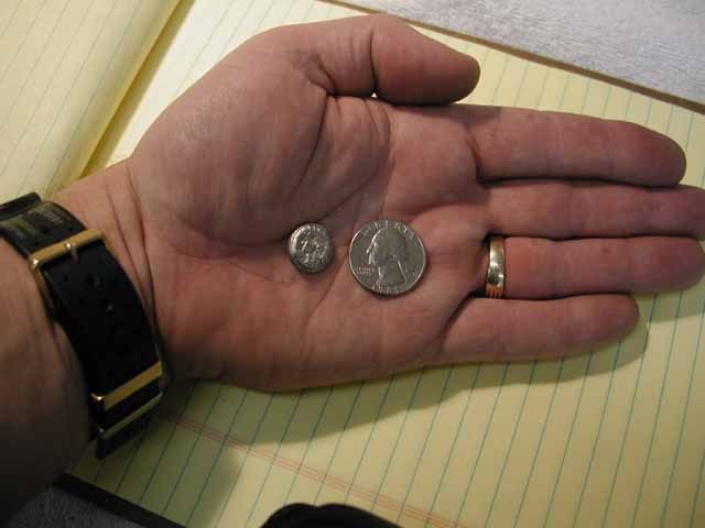
First quarter from the Rev2 machine.
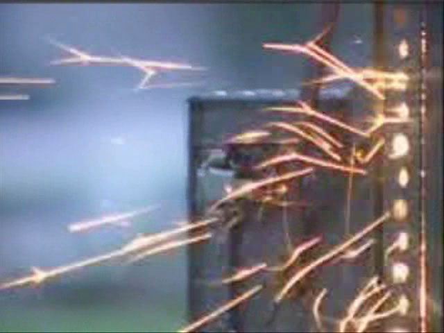
I would occasionally see sparks when the machine fired and I thought they were just escaping from the seams in the containment box. As I was reviewing some video shot by G4TV I realized that the arcing was coming from the containment but from a metal support directly adjacent the capacitor. The amazing thing is the cap and steel support are both tied together mechanically and electrically only a few inches away from the arcs. How can this be developing a potential high enough to arc??? More to come...
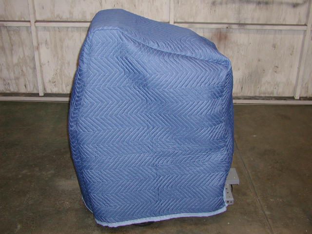
And after all that work it deserves a nice new cover to keep it clean and protected.