![]()
![]()
![]()
![]()
![]()
|
|
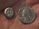
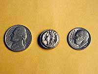
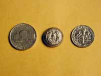
Shrunken Quarter
The PDM Machine
This picture shows the front of the machine. On the lower left is the HV Power Supply. On the lower right is the control box which houses the control circuitry, low voltage transformer, and air compressor.
This shows the right, rear, and left views of the machine. If you look closely you can see the buss bars, safety lockout, trigatron, and discharge resistors,
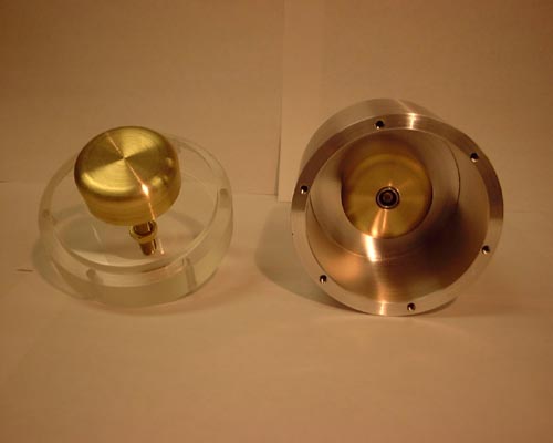
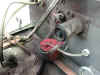
Work Coil
The picture on the left shows a work coil in place and ready for a shot. The second picture shows the results after the shot. If you look closely you can see the shrunken quarter just to the right of the wooden dowel. also note the wire shrapnel all over the inside of the containment.
What it does
(This picture was swiped from Ross-O's site)
How it Works The Quarter Shrinker uses a technique called high velocity electromagnetic metal forming, or "Magneforming". This technique was originally developed by the aerospace industry, and has been popularized by Aerovox, Grumman, and Maxwell. It involves discharging a high energy capacitor bank through a work coil to generate a very powerful, rapidly changing magnetic field which then interacts with and "forms" the metal to be fabricated. It only works with metals of relatively high conductivity, such as copper or aluminum alloys, although it will work to a more limited extent with sheet steel. The large current that's induced into the outer rim of the coin may reach a million amperes or more. Since the initial energy is in the range of 3,500 - 10,000 Joules, the instantaneous power is awesome, and for a brief instant is roughly equal to the electrical power used by the entire city of Chicago. The repulsion forces between the work coil and the coin create a huge radial inward compressive force on the coin that easily overcomes the yield strength of all the metal(s) in the coin, causing it to plastically deform the coin into a much smaller diameter. At the same time, a similar outward radial force literally explodes the work coil. As the work coil expands, the wire eventually fragments, and pieces of the coil are then forcefully ejected outward with the force of a small bomb. Once the coil disintegrates, any residual magnetic or electrostatic energy remaining in the system is transferred into the resulting ball of blue white plasma that fills the blast shield or is dissipated by bleeder resistors. (The description above was swiped from Bert Hickman's site)
Block Diagram
Safety and reliability were primary factors in this design.
Schematics
These show how things are actually hooked up.
Calculations This workbook gives energy calculations as they relate to a particular charge voltage. It also provides peak and average power dissipation calculations for the bleeder resistor network.
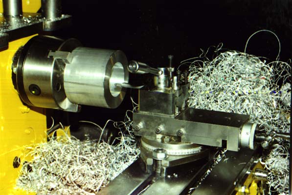
Construction
High Voltage Capacitor Charging Supply
This is a 34kv power supply which is designed to charge capacitors at a rate of 1kJ per second. I've limited the controller so it's only capable of 22kv. This will help prevent over volting the capacitor.
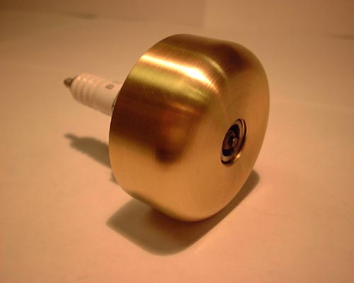
Trigatron
A Trigatron is a fast acting, high voltage, high current switch which is triggered by a high voltage arc inside of the main body. This design uses a modified spark plug as the trigger electrode.
This trigatron is one of two units I hand fabricated. The other unit is installed in Ross-O's PDM machine.
Trigatron Firing Circuit
This method was recommended by Bert Hickman. It is simple, inexpensive, and will produce about 1" arcs from either a standard ignition coil or a HEI coil. The light dimmer can be found at Home Depot or similar stores.
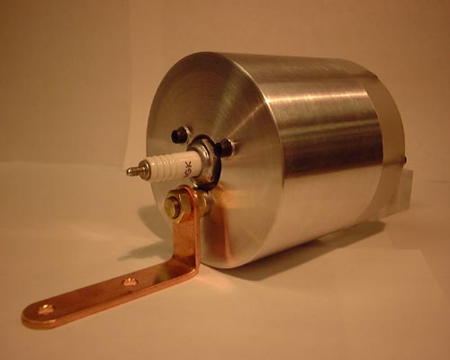
Pulse Discharge Capacitor
This unit is capable of storing and discharging over 67kJ of energy. Shrinking of a quarter takes only 4-9kJ. This is an extremely deadly and deceptive component. Utmost care need to be taken whenever working with or near this capacitor.
Main Control Box
This box houses the 240v mains isolation transformer which also provides 120vac to the Trigatron firing circuit. It also contains the power supply control board, charge voltage adjustment, status indicators, air pump, air reservoir, pneumatic switches, and other control circuitry.
Pneumatic Controller
This is the hand controller which allows the operator to override the interlock, charge, and fire the PDM machine. Safety is a primary concern with this machine so I've designed it with complete isolation for the operator. To accomplish this I use air pressure to control the functions eliminating any wires between the operator and the machine.
Cart
I'm attempting to build a cart that is half hand truck and half cart. If all goes well it will tip back on two wheels for moving between locations. It will also have a third front wheel to ease in positioning while in use.
All the major components are mounted. I now need to disassemble it, paint the mounting board, then re-assemble.
Containment
The containment box is made of 1/4" steel diamond-plate. The lid has overlapping seams to prevent fragments from slipping between the mating surfaces. The first shot shows the inside with the lid removed. The second shot shows the unit with the lid installed. I still need to add the catches, HV insulator and binding posts.
Some better pictures of the containment and how the lid operates.
Completed PDM
The first picture shows it nearing completion. The second and third pictures show the completed unit (minus some lexan shielding around the top HV wiring). The black cable on the left is four air hoses in a corrugated sheathing. These hoses carry supply air and control signals to/from the hand-held pneumatic controller.
|
|
Questions and comments Copyright © 1997,2006 Brian D. Basura This site was last updated 04/02/06 |